Tutorial-01: Stepped Shaft CAD model development using Free CAD software as per FEA simulation input requirement
CAD File of Stepped Shaft:
Figure 1 Stepped Shaft having Dimensions
Steps required for CAD making process using FREE CAD software:
Steps I: Start the software and select "part design" module in freeCAD software, it is assumed that you have already installed freeCAD software (Version should be latest )
Figure 2 Start menu of FreeCAD software (Version 0.19)
Step-II: Select "Create body" option in Part Design module of the FreeCAD software
Figure 3 Create Body option for making body in FreeCAD software
Step-III: Create Sketch, after selecting of creating body option, time to select "create sketch" option for making the sketch for the stepped shaft.
Figure 4 Create Sketch option selection
As you click on create sketch command, a popup window will open, in which you must be required to select one base plane for making the first sketch. (Green Color is the confirmation of the selection of the base plane for making the sketch)
Figure 5 Base Plane Selection for making Sketch
Step IV: Manage "Edit Controls" in sketch window
Figure 6 Manage Controls for making Sketch
Note: It is not mandatory to select these controls but from my suggestion, please select
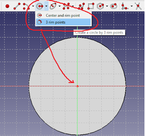
Step V: Create Sketch, as seen in figure 1, the center section of the shaft has a 40 mm diameter and length is equal to 100, so in sketch mode, a circle command is required to select for making the circle of 40 mm diameter
Figure 7 Circle command and the making of circle
As seen in figure 7, the circle has no proper dimension because of no dimension constraint, and that's why this sketch has one degree of freedom. You can make a circle of any diameter as your mouse movement and don't worry dimension will provide in the next step.
Step VI: Dimension Constraint (Diameter Constraint)
Figure 8 Diameter Constraint
As seen in figure 8, select diameter constraint and give 40 mm diameter in the sketch window
Figure 9 Diameter constraint and its value
As seen in figure 10, if the sketch color is turned in green color its means the sketch is a "fully Constrained" sketch.
Figure 10 Fully Constraint Sketch (Green Color)
As seen in figure 1, the midsection of the shaft is 40 diameter circle which has 100 mm length, so now time convert this sketch into the 3D model so close the sketch window and start to work in the part model window, final sketch in part design window with model tree in (Combo View)
Figure 11 Combo View after sketch making
Step VII: making 3 D object using PAD command
Figure 12 Selection of PAD command for making the 3D object
PAD command help to make a 100 mm long shaft which has 40 mm diameter.
Figure 13 Length option in PAD command
The same steps are followed for making a full stepped shaft but this time new sketch will be made on the face of the shaft which we already made, so you should select any face of the shaft and select create sketch command again
Figure 14 Create Sketch on Face
As seen in figure 1, in the stepped shaft after making a shaft of 40 mm diameter, time to make a shaft having 30 mm diameter with a length of 75 mm on both sides of the faces of the innermost shaft section.
Like the previous step manage the "Edit Controls" command in Sketch Window and set as the previous option (Figure 6)
Make a circle with 30 mm diameter and make it fully constraint by using diameter constraint
Figure 15 Create Sketch on Face of the 40 mm shaft
After creating a circle on the selected face time to give diameter constraint for 30 mm diameter.
Figure 16 Diameter constraint for 30 mm diameter on the face
A fully Constraint sketch is shown in figure 17 and then close the sketch command and select PAD command for making the 75 mm length 3D object.
Figure 17 Fully Constraint Sketch for 30 mm diameter
Step VIII: Final 3D stepped Shaft
Figure 18 3D object of length 75 mm using PAD command
A shaft of 30 mm diameter having 75 mm length is shown in figure 19 using PAD command.
Figure 19 Give length of 75 mm in PAD command
Repeat all steps like previous steps and make the final stepped shaft as shown in figure 1. The final stepped shaft made by FreeCAD is shown in figure 20.
Figure 20 Stepped Shaft made in FreeCAD software
Video Tutorial for CAD modeling of Stepped Shaft using FreeCAD software


Comments
Post a Comment