
Ceiling Fan Simulation in a Room Using Ansys Fluent | Adding Fan Boundary Condition in CFD

Ceiling Fan Simulation in a Room Using Ansys Fluent | Adding Fan Boundary Condition in CFD

Introduction

In this tutorial, we will perform a CFD simulation of a ceiling fan inside a room using Ansys Fluent. We will also learn how to add a fan boundary condition to simulate airflow behavior accurately.

Step 1: Setting Up the Geometry in Ansys

  1. Open Ansys Workbench and create a new Fluid Flow (Fluent) Project.

  2. Use SpaceClaim or DesignModeler to create the room and fan geometry.

  3. Ensure that the fan blades are modeled properly or import the 3D fan model.


Step 2: Meshing the Model

  1. Open the Meshing Tool in Ansys.

  2. Apply a fine mesh around the fan for better resolution.

  3. Use inflation layers near walls for accurate boundary layer calculations.


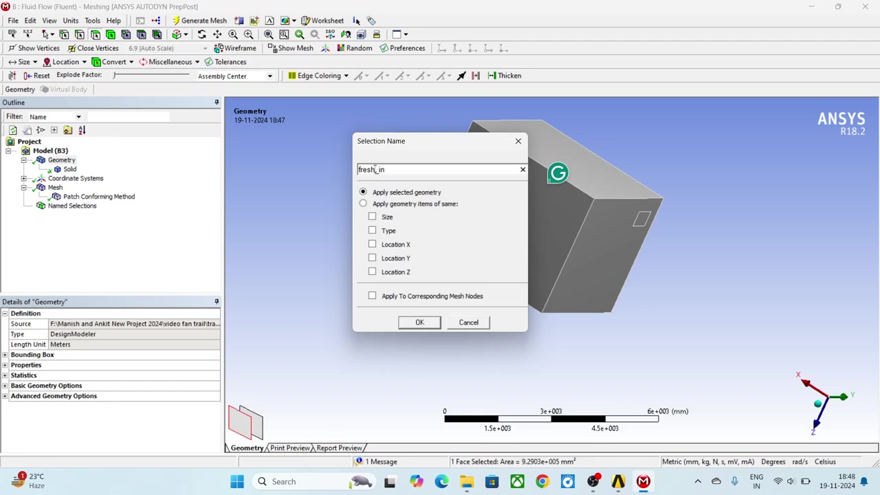
Step 3: Defining the Boundary Conditions

  1. Open Ansys Fluent and import the mesh.

  2. Set the room walls as no-slip boundaries.

  3. Define the fan region and apply the fan boundary condition.

  4. Set the inlet velocity and outlet pressure as per simulation requirements.


Step 4: Setting Up the Solver

  1. Choose Pressure-Based Solver with Turbulence Model (e.g., k-epsilon).

  2. Enable Gravity Effects for realistic airflow behavior.

  3. Set the solution initialization to Hybrid or Standard.

Step 5: Running the Simulation

  1. Start the iterations and monitor residuals.

  2. Check for convergence criteria (e.g., steady-state residuals below 1e-3).

  3. Visualize velocity contours, streamlines, and pressure distributions.


Step 6: Analyzing the Results

  1. Evaluate the airflow distribution in the room.

  2. Compare results with experimental or theoretical values.

  3. Optimize the fan placement and speed for efficient ventilation.


Conclusion

This tutorial demonstrated how to simulate a ceiling fan inside a room using Ansys Fluent. By adding a fan boundary condition, we could accurately analyze airflow patterns and optimize ventilation efficiency.


Comments

Popular posts from this blog

New Era of AI based Chat Tools (chatbot): ChatGPT In Hindi : Explanation...

FDS-01: SIMPLE FLUID FLOW ANALYSIS USING FDS (FIRE DYNAMICS SIMULATOR) TOOL

FDS-01: SIMPLE FLUID FLOW ANALYSIS USING FDS (FIRE DYNAMICS SIMULATOR) TOOL In this tutorial a window is created which is treated as inflow of air with velocity of 2.5 m/s having temperature of 5 C. The outflow conditions is treated at top of the office, and the boundary condition is set as open to atmosphere  The steps are followed in this tutorial are listed below::   Step I: create header syntax file to start program in FDS software.   &HEAD CHID='office'/ Note: office is user defined name of FDS function/ file.   Step II: create syntax for simulation flow time.   &TIME T_END=15.0 Note: 15 sec is simulation flow time, which is solved in FDS software.   Step III: create syntax for initial temperature of domain.   &MISC TMPA=45.0/   Note: 45 C is initial room temperature, which is provided in this tutorial. Following three syntax is must for every FDS function.   Step IV: Create syntax for geom...

Tutorial 01 Heat transfer analysis in Pipe Flow in Elbow pipe structure OPENFOAM

 Title : Heat transfer analysis in Pipe Flow in Elbow pipe structure Figure 1.1 Meshed domain of elbow section Problem Identification This problem is simple pipe flow problem, in which air is flow in elbow section from two inlet conditions having different flow and energy boundary conditions. (See the following figure). Air properties are selected from literature material available in digital medium. “ buoyantBoussinesqPimpleFoam ”  is selected as solver for this problem. Open Foam software is installed on Win 7, provided by FSD blueCAPE Lda: http://bluecfd.com / Note : This tutorial is not endorsed/ supported by any provider of software's which are used in this tutorial. This tutorial is made for educational purpose only. Figure1.2 Different Boundary Conditions The simulation is solved in ambient conditions at transient flow scheme available in selected solver. Pre-Processing This problem is selected as turbulent flow problem, so the solver must...